
Day 1 Community Design Challenges
How do I get started?
Pick out a challenge from below and start building! All the challenges require that Ignition is installed, so download and install Ignition 8.1. There's also a gateway backup that you can download here that will be required for many of the challenges. It contains Tags and other resources that you'll find necessary to complete some of the prompts. It's best to load this backup before you start any challenges since a Gateway Restore will wipe out any work you already have.
If you already have Ignition installed, make a backup of your Gateway before starting.
Download the CDC Gateway backup here.
Easy Challenges - 5 XP each
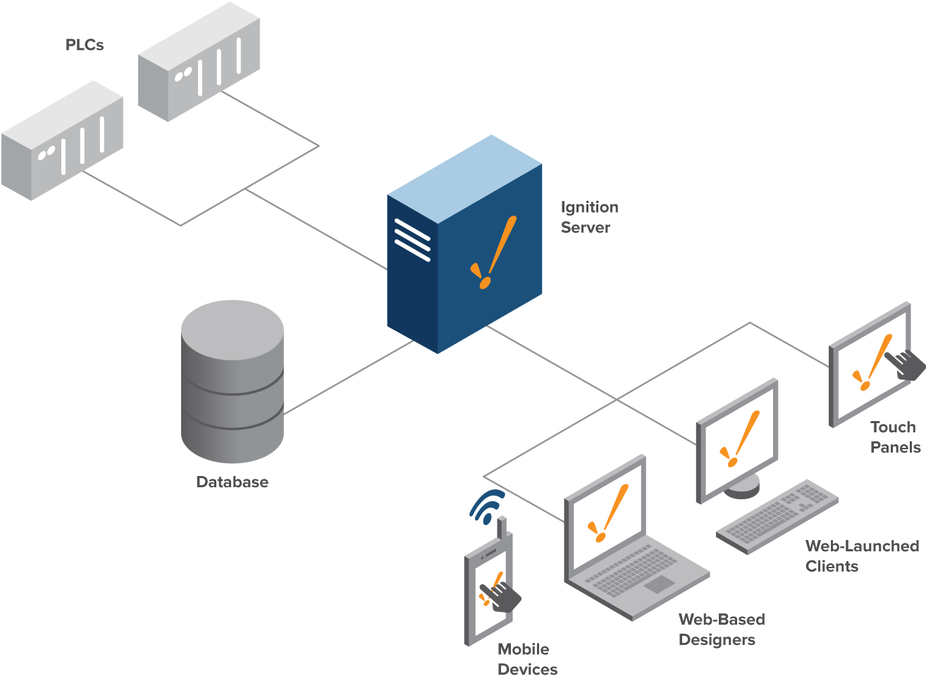
Architecture Builder
Install and use the Architecture Builder tool in the Ignition Exchange.
Prompt:
Download and install the Architecture Builder from the Ignition Exchange. Ignition Architecture Builder
With it, draw a diagram of the Single Server Install standard architecture.
Create and Apply Styles
Create reusable styles for your project.
Prompt:
Create a Header style class with the following attributes: 18pt, bold, centered text, with a border.
Create a Body style class with the following attributes: 12pt, italic, Arial, Color: 7A7A7A
Create a Background style class with the following attributes: background color: CCE7FF
Apply all styles to the Add Styles/Add Styles view.
- The Header style should be applied.
- The Body style should be applied to all non-header text on screen.
- The Background style should be applied everywhere except the header.
Make a UDT
Create a UDT and matching Tag instances.
Prompt:
In the Packaging folder of the connected Simulator device, make a UDT definition based on the Line object.
Create a folder named UDT in the default Tag Provider.
Create instances for each Line in the PLC.
Medium Challenges - 10 XP each
Project Inheritance
Create a set of linked projects where one inherits the resources of the other.
Prompt:
Create two new Ignition projects, named Parent and Child. Set them up so one is a parent project and the other is a child project which inherits from its parent project.
In the parent project, create a new system library with at least two functions. The functions can do whatever you’d like, but use other Ignition system functions within them. For example:
- Prompt for a user input.
- Read or write a tag.
- Display system information, etc.
In the child project, demonstrate usage of the two parent system library functions.
Template Canvas Component
Create a Grid of clickable buttons in the Template Canvas component.
Prompt:
Create a small Vision template to be used as a button. The background of the button should be a neutral gray color.
When the button is pressed using the mouse, the button should change from a neutral gray color to another color of your choice and change back to gray when the mouse is released.
Use a Vision Template Canvas component to create a 3 by 3 layout showing 9 buttons.
Draw a Moving Train with the Drawing Tools
Draw a train that moves across a Vision window.
Prompt:
Draw a simple train using the Vision drawing tools.
Animate the train so it moves horizontally across the window.
Add a start/stop control to start/stop the movement.
Hard Challenges - 15 XP each
Dashboard Save
Save and recall configured screens using the Perspective Dashboard component.
Prompt:
A Dashboard view and a few widgets have been created in the Dashboard folder in Perspective. Create a way to be able to save configurations.
Add a component to show which saved states are available.
Create a button to load the selected saved dashboard.
CSV Import to Table
Create the ability to select a file and import its contents.
Prompt:
In either Vision or Perspective, provide some means of selecting a desired CSV file and loading it into a table on screen. The first line of each CSV contains header labels.
Data files:
- ICC2025_datatypes.csv
- ICC2025_inventory.csv
- ICC2025_population.csv
- ICC2025_sacramento.csv
- ICC2025_sample.csv
Rock-Paper-Scissors
Create a Rock-Paper-Scissors game for two people.
Prompt:
Create a rock-paper-scissors game that allows 2 different players using separate clients/sessions to play against each other.
Users must be able to select their weapon.
A winner (or tie) must be displayed once both weapons are selected.
ProveIt! Virtual Factory Day 1
Observe the UNS structure of the Virtual Factory in the Prove It data, and create appropriate UDTs from some of the data.
If unfamiliar, review key concepts about organizing operational data into a Unified Namespace (UNS): virtualfactory.online
In the Tag Browser, browse devices and identify the “Virtual Factory” device connection which represents tags for an abstracted factory inspired by ProveIt!
Assume the Semantic Hierarchy for this factory is being standardized using following the structure:
Virtual Factory UNS: Enterprise \ Site \ Area \ Line \ System \ {Category} \ Tag
- Enterprise: Root, represents the organization responsible for production
- Site: Physical Location, in this case name of the city the production facility is located in
- Area: Functional Area, what the underlying tags are used for
- Line: A specific production line, or cell, that usually includes multiple pieces of equipment and data collection systems
- System: A specific system of data collection, or specific equipment system, for the production line (ex: ERP, MES, SCADA, Edge, etc.)
- Category: A sub-category of a system, like a folder, for aggregating similar tags (ex: KPIs, Maintenance, Quality are each a Category within MES)
- Tag: A useful datapoint
*The Category is optional and some tags exist directly within a System folder.
**Certain important Tags can exist at even higher levels of the UNS, not just level 7. These can be used for key compliance, performance, or quality tracking as well as general information. (ex: Each Site has a tag for tracking the manager of that location)
Based on the Semantic Hierarchy of the “Virtual Factory” device, note in a text file the number and names of the:
- Sites
- Areas per Site
- Lines per Area
- Systems per Line
- Categories per System (if applicable)
Of the Systems and Categories you identified, categorize each of them generally as one of the following:
- Descriptive: static informative data, describing an asset or system
- Functional: operational functions, systems performance, or business processes
- Informative: modeled data, actionable information for dashboards
In your opinion, if you had to label this hierarchy with a single option, which would you choose and why: Descriptive, Functional, or Informative?
Prompt:
In your tag browser, create new folders in the UDT section with the following names:
- Categories: For UDT instances capturing Tags within the Categories you listed
- Systems: For UDT instances capturing Tags within the Systems you listed (some of which will have nested Categories)
Create UDT Definitions in the appropriate folder for the Categories and then the Systems that include all of the child Tags seen in the OPC Tag Browser. The child Tag definitions should have dynamic OPC Item paths by using UDT parameters for the parent levels in the Hierarchy. Create the Categories first, and add them as member instances to the appropriate System UDT definitions (ex: The Edge System includes the Process Category).